Repairing the Apollo Ultrasonic Oil Monitor receiver
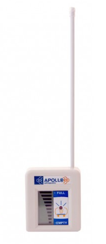 One day I went to check the oil level on my Apollo Ultrasonic Oil Monitor but the display was blank.
The guarantee had just expired.
So I unplugged it and left it for a while and then tried it and it seemed to work ok.
But after a while it blanked out again. After a time it got worse and I would unplug it
but when I plugged it back in the display would flash erratically or it would only stay
on for a few minutes.
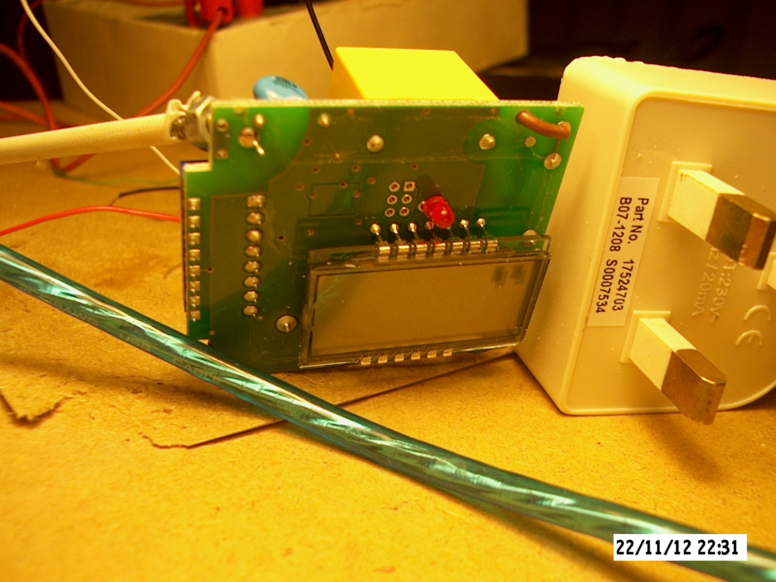
So I decided to have a go at fixing it. I started by sawing the case in half with a junior hacksaw.
It took a lot of sawing, the plastic is tough.
I used a USB power supply instead of the Apollo's internal power supply. It works well but whether
you should do the same is up to you to decide. I intend to use it only when I want to check the oil level.
I'll plug it in and give the unit fifteen minutes to get the current oil level reading and then unplug it.
The information here is just to help would be DIY fixers. I take no responsibility for anything you do.
Any risk associated with DIY fixing this unit is yours.
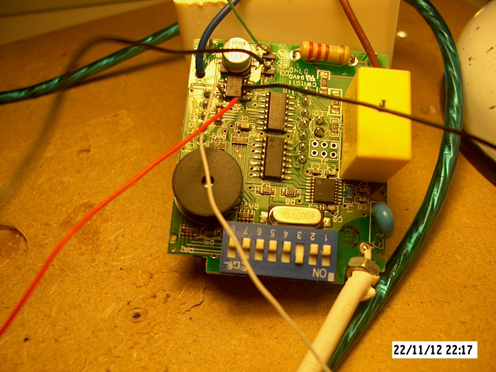
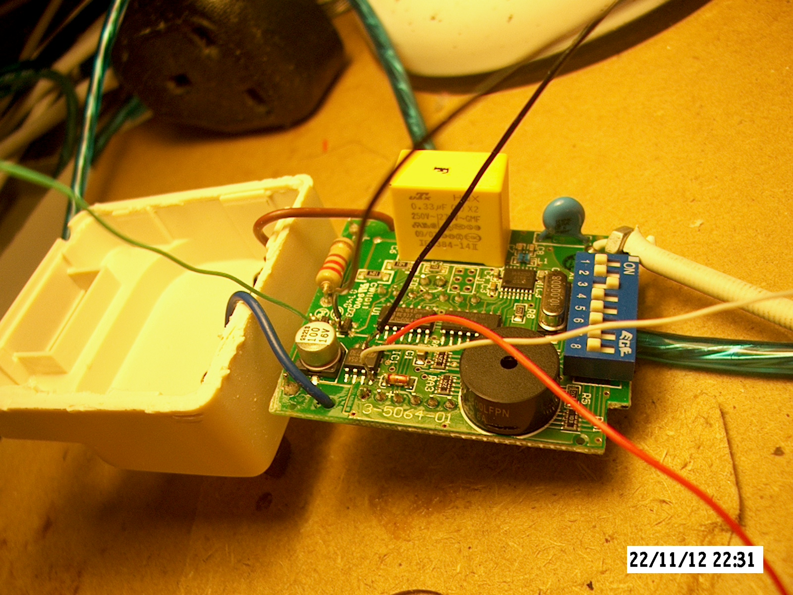
This is a photo of the printed circuit board from inside of the unit.
In this photo I have soldered on some extra wires to make it easier to measure the power supply voltages.
The photos on this web page are a higher definition than you see here.
If you zoom the web page to 200% you will see more detail in the images.
If you work on this board with the mains power on be careful of the big resistor and surface mount resistor in the top right corner of the board they have 240 volts A/C on them.
The mains voltage is dropped down through the two surface mounted resistors below the big resistor and connects to a bridge rectifier in the middle top of the PCB.
I have soldered two wires onto the inputs to the bridge rectifier and on my PCB it reads 5.0 volts A/C. I think this needs to be about 8 volts A/C for the unit to work correctly.
The DC output from the rectifier goes to pin 8 of a 78L05A 5 volt regulator chip. I have a white wire soldered there and my PCB reads 3.68 volts there. I think this needs to be about 7 volts D/C for the unit to work correctly.
The output on pin 1 where I have soldered a red wired reads 2.25 volts on my PCB. This should be 5 volts.
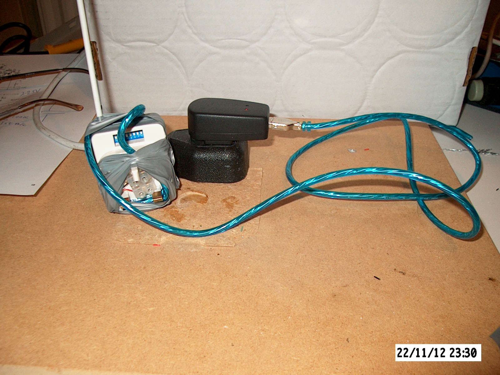
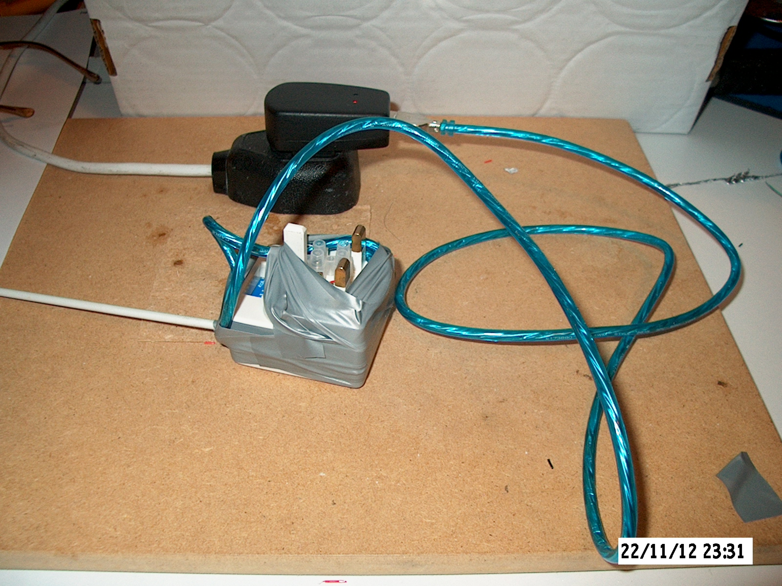
I re-assembled the unit leaving one wire to pin 3 (GND) and one wire to pin 8 (Vin) of the 78L05A 5 volt regulator chip.
I taped up the unit and then cut up an old USB cable and soldered it's GND and 5V wires to the two wires that I fed out of the unit.
I use a 0.5 Amp USB power supply that you can buy on eBay for a pound to supply 5 volts.
This gives me about 4 volts output from the 78L05A 5 volt regulator chip. It's a bit low but it's enough to work the unit.
I checked the components in the units power supply but could not identify which was causing the low voltage. I suspect that perhaps the capacitor in the top left corner of the PCB might be leaking.
It looks like a electrolytic capacitor. It's stupid to use that type in a device that's normally on 24/7 because they have a limitted life span. To extend the life of these units consider not using them 24/7.
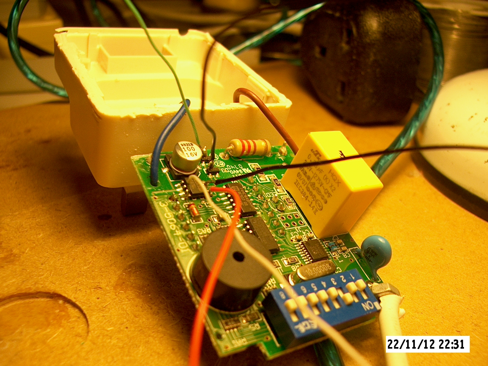
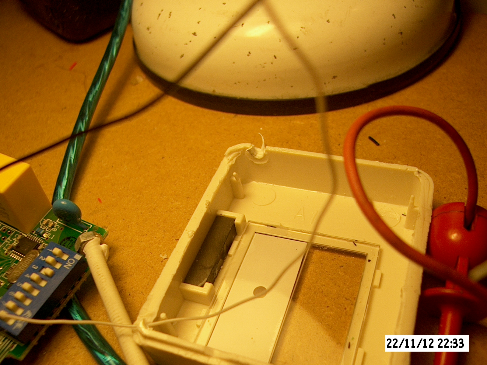
The black piece is a magnet. This is used to match the transmitter and receiver. It must operate a reed switch in the transmitter.
This might open up the possibility to match a transmitter and receiver when the transmitter is already installed in the tank.
If you place a magnet next to the installed transmitter it might match. You have two minutes after the receiver has been turned on to do the matching.
My home page